What is OpenPowerNet?
OpenPowerNet is a
traction power supply and train performance simulation software developed by Institut
für
Bahntechnik GmbH, BO Dresden, and is certified according EN 50641:2020. OpenPowerNet does
the traction Power Supply
Calculation in module PSC as well as the Advanced
Train Model
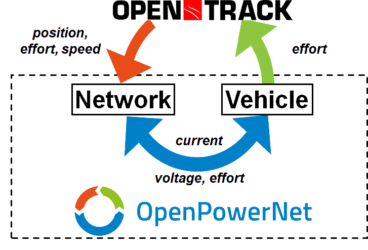
simulation in module ATM. The operational simulation is done by OpenTrack
in
co-simulation with the electrical simulation. OpenPowerNet has a
retroactive
effect to OpenTrack.
OpenPowerNet is developed by Institut für Bahntechnik GmbH, BO Dresden as an in-house tool. Since July 2009 a commercial and since March 2010 a academic license is available. In case you are in need of a traction power supply simulation respective simulation tool please contact us. We provide OpenPowerNet licenses as well as the service to simulate and analyse traction power supply systems.
OpenPowerNet main functionality:
- Load flow analysis for 1AC, 2AC and DC networks
-
Modelling of
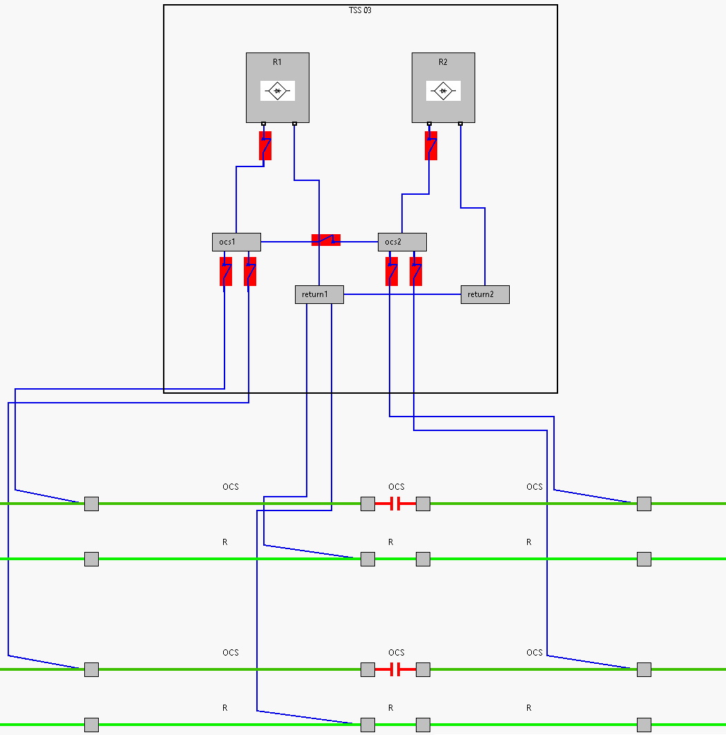
- Power supplies such as rectifier/inverter, transformer, converter (SFC)
- Controlled rectifier and inverter
- Wayside energy storage for stabilisation of line voltage or energy saving
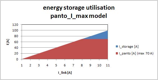
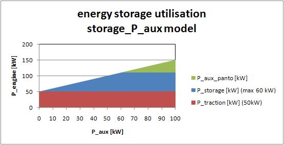
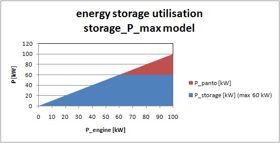
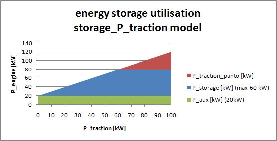
- Onboard energy storage chargeable from OCS and allowing running on OCS free track sections
- Booster transformer
- Voltage limiting device
- Engines with tractive and braking current limitation, power factor versus voltage, recovery braking, eddy current braking, onboard energy storage, ...
- Engine with multiple propulsion systems, e.g. AC and DC
- Consideration of coasting behaviour of the courses
- Calculation of
- Applicable tractive effort for OpenTrack
- Braking effort and recovered energy
- Magnetic coupling between conductors, allowing to evaluate the effect of conductor position onto loop impedance and magnetic field
- Short circuit currents for any position along the track
- Line voltages for constant current loads to analyse the electrical network
- Energy balance
- Visualisation
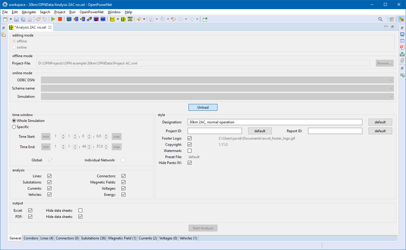
- Analysis Tool generates Microsoft Excel and PDF files
- User defined translation can be used to generated files in any language.
- Shows compliance to standards
- EN 50163: evaluation of minimum line voltage and maximum time above/below threshold voltage
- EN 50122-1: evaluation of maximum touch voltage
- EN 50122-2: evaluation of stray currents
- EN 50388: calculation of Umean useful (zone) and Umean useful (train)
- and threshold violation regarding
- Rating of devices such as rectifiers and transformers
- Rating of feeder cables regarding load demand
- EMC / EMI
- Induced voltage into cable shields or any parallel structure
- ...
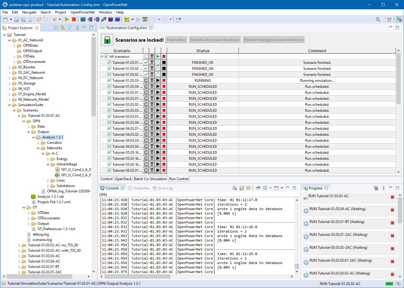
- Convenient execution of multiple simulations and analysis managed by the Automation Config.
What's
 in version 1.15.2 ?
- This is a bug fixing release only.
- More detailed information is available at the Release Notes.
Graphical User Interface
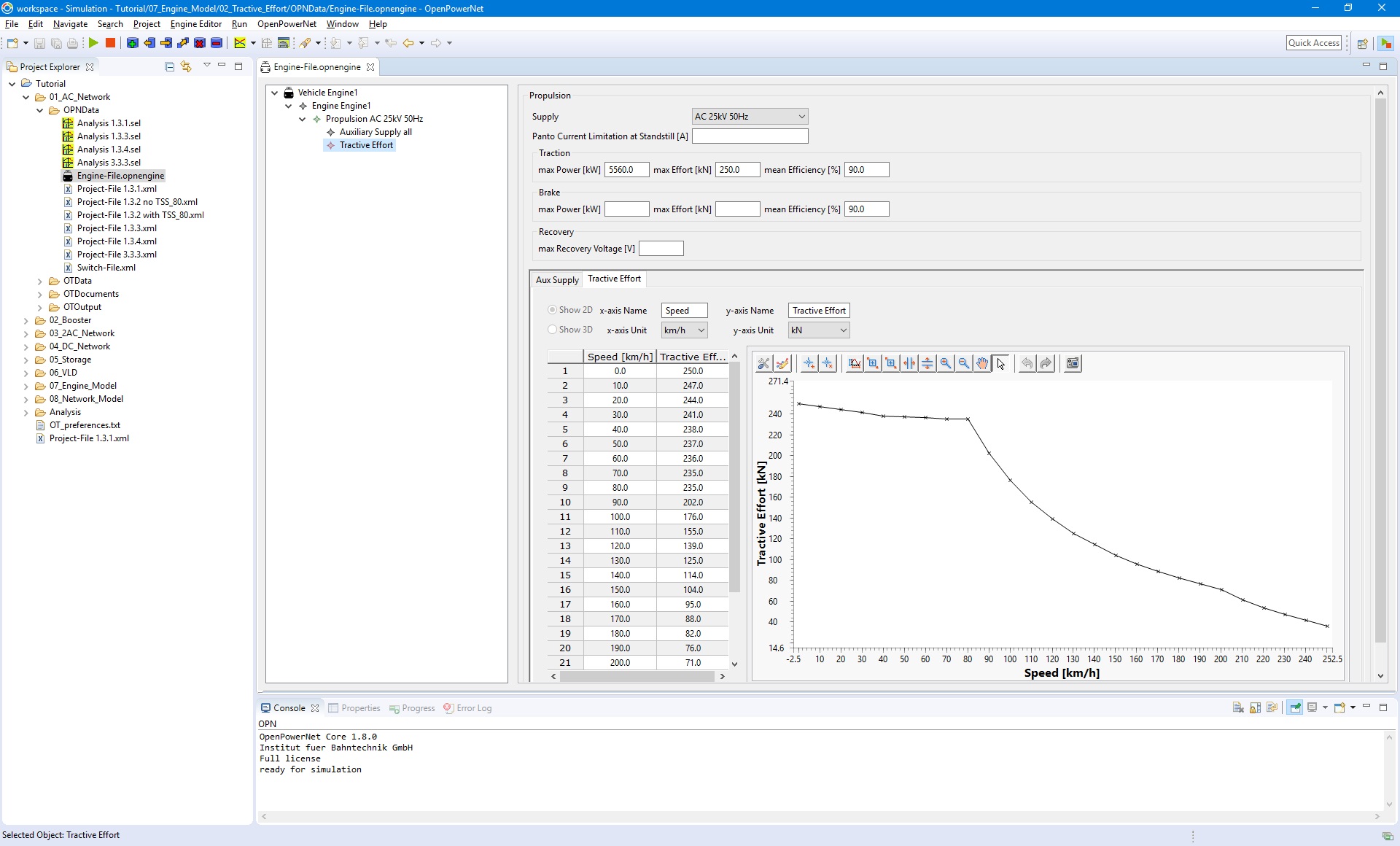
Engine Editor
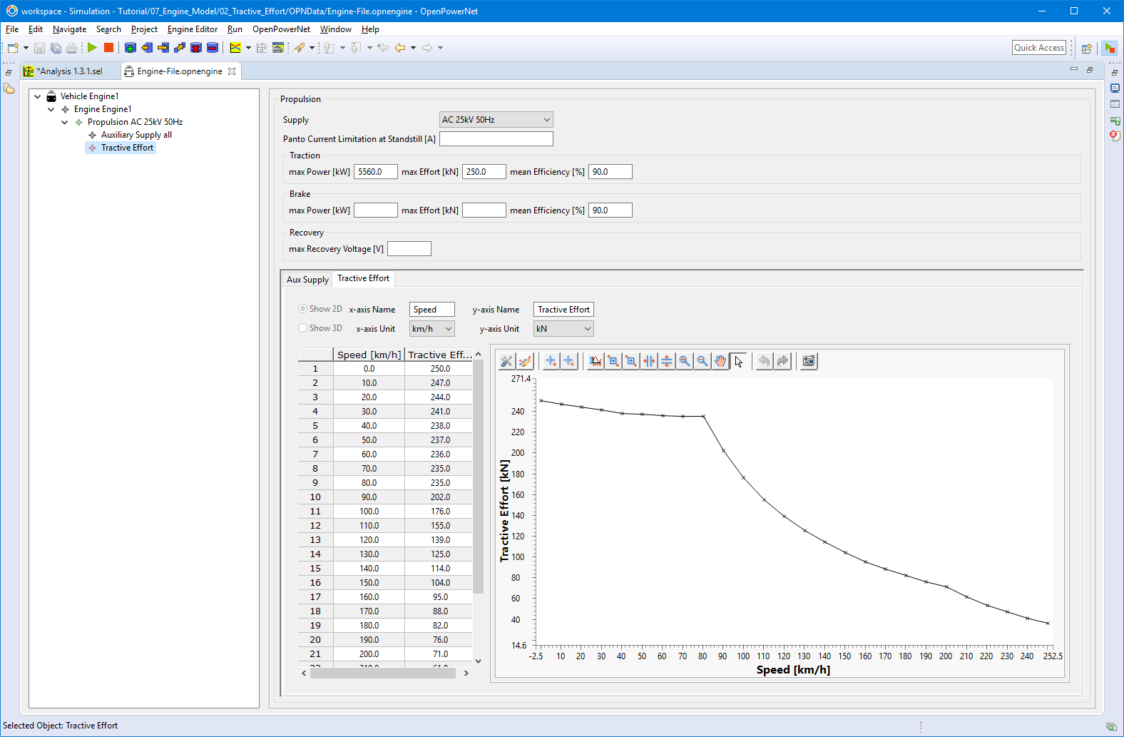
Analysis Tool
 Automation Config
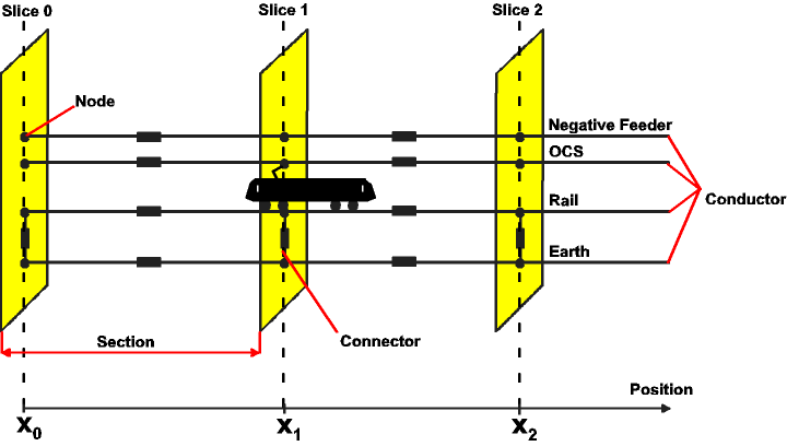
Software Structure:
Network Model:
Substation Model:
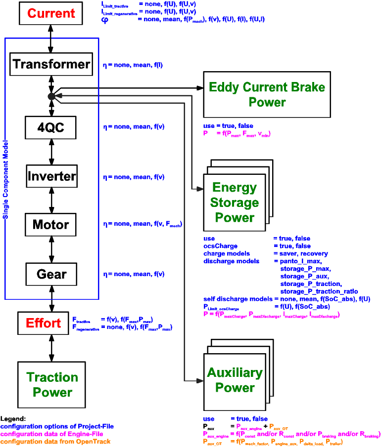
Engine Model: Single Components
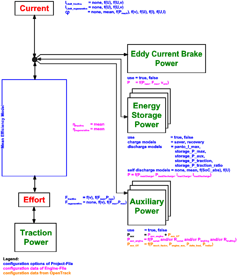
Engine Model: Mean Efficiency
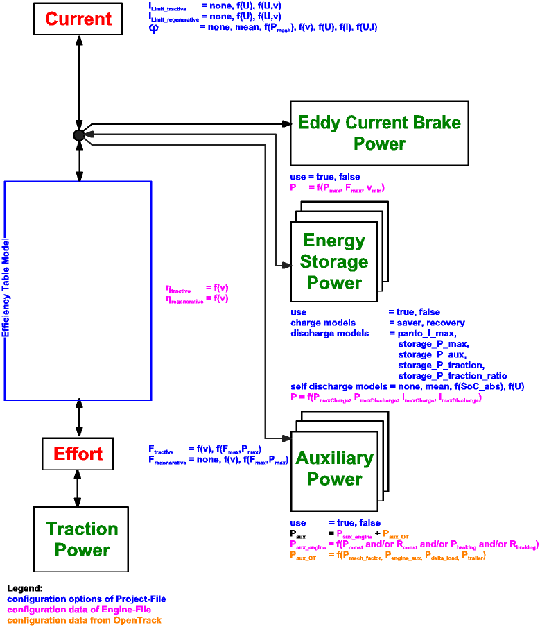
Engine Model: Efficiency Table
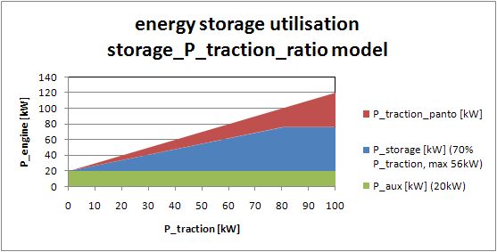
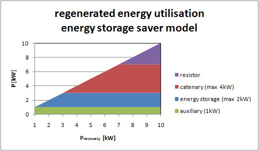
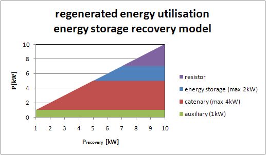
Engine Energy Storage Charging Models:
Engine Energy Storage Discharging Models:
